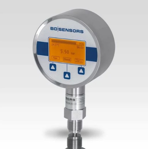
The DL 01 leak testing pressure logger series delivers elite performance for the most demanding calibration, test technology, leak testing, and pipeline monitoring tasks. Engineered around a flexible modular sensor concept, this instrument integrates an advanced data logger and a high-resolution graphic display within a robust 100 mm stainless steel housing. It accommodates an expansive measurement range spanning from 0…100 mbar up to 0…400 bar across both gauge and absolute pressure formats, ensuring an exact fit for diverse industrial and laboratory frameworks.
Product Parameters
- Nominal pressure range: Offers comprehensive coverage from 0…100 mbar up to 0…400 bar to suit low-pressure and high-pressure industrial environments.
- Measurement formats: Available in gauge or absolute pressure configurations based on application needs.
- Accuracy class: Delivers high-precision performance with a standard accuracy of ≤±0.1% FSO for ranges ≥0.4 bar, and ≤±0.25% FSO for ranges <0.4 bar.
- Housing specification: Built with a rugged 100 mm stainless steel 1.4301 (304) housing that provides IP 66 ingress protection against dust and water jets.
- Media-wetted materials: Constructed using premium stainless steel 1.4404 (316L) or 1.4435 (316L) for the pressure port and diaphragm, with option-dependent FKM seals or a fully welded structure.
- Data logger capacity: Features an internal storage matrix capable of recording up to 600,798 discrete pressure and sensor temperature values.
- Sampling interval rates: Provides highly adjustable logging intervals from 1 second to 99 days, fixed times, or high-speed sub-second bursts at 20 ms intervals.
- Power supply architecture: Powered independently by three 1.5 V AA batteries, offering a standard operational life exceeding 2,000 hours and a standby lifespan of at least 5 years.
- Digital communication interface: Features an integrated USB 2.0 interface for secure data transfer, diagnostic lookup, and device configuration via companion PC software.
Product Description
The series represents a milestone in standalone pressure measurement, purposefully engineered to blend laboratory-grade precision with industrial durability. At its technical core is a modular sensor pairing system that establishes an automatic digital link between the display unit and the underlying pressure transmitter module. This design isolates mechanical line stress from the electronics while allowing the gauge to handle up to 100 million load cycles over its operating life. For deployments in volatile atmospheres, the instrument offers certified intrinsically safe hardware options, including a dedicated conductive front foil variation engineered for safe operation directly inside Zone 0 environments.
A large 55 x 46 mm graphic LC display serves as the central control interface, utilizing a 128 x 64 pixel resolution to show real-time metrics, system statuses, and configurable parameters cleanly. It includes a 100-segment analog barograph for visual pressure tracking, a high-visibility primary value readout, and a secondary temperature display accurate to ±2 K. Users can interact with a closed, multi-tiered menu using three front-facing buttons to change pressure units, toggle low-power standby modes, and program adjustable backlight cycles.
The integrated data logging engine handles specialized testing procedures, such as line monitoring and decay-based leak detection, without requiring external equipment. When switched to leakage mode, the gauge monitors and displays real-time pressure changes over a user-defined testing window. Once the test finishes, it shows a clear compliance status directly on the display panel. Using the integrated USB 2.0 port and companion software, operators can download saved logs, review data tables, scale charts freely, and generate formal PDF inspection reports.
Product Features
The product features a suite of advanced technical capabilities designed to ensure precision, reliability, and ease of use in demanding industrial environments, with each feature engineered to enhance data accuracy, operational security, and maintenance efficiency.
High-Performance Accuracy
The device delivers elite, class 0.1 precision by employing sophisticated limit-point adjustment algorithms. These advanced calculations actively minimize measurement deviations caused by non-linearity, hysteresis, and repeatability, ensuring laboratory-grade reliability even when operating in harsh, ruggedized industrial environments.
Dedicated Leak Test Engine
Engineered to streamline field operations, the built-in leak test engine provides a comprehensive evaluation interface. During active testing, the display dynamically tracks and illustrates pressure drops over time, culminating in a clear, automated validation result that confirms system integrity without the need for additional external diagnostic equipment.
Flexible Unit Selection
Operators benefit from extensive versatility through native unit conversion, allowing real-time parameter display in diverse formats such as bar, PSI, mbar, mH2O, inHg, hPa, kPa, MPa, and kg/cm2. The system also supports custom user-defined scales, ensuring seamless integration into varied international and specialized industrial workflows.
High-Speed Data Capture
To meet demanding diagnostic requirements, the instrument supports an accelerated burst recording frequency of 50 measurements per second. When configured with 20 ms interval logger settings, this capability allows for the precise capture of transient pressure events that slower, standard instruments would likely miss.
Smart Password Protection
Data integrity and security are prioritized through a programmable four-digit alphanumeric password lock. This feature prevents unauthorized tampering with menu configurations or critical calibration settings, protecting saved log data from unintended modification while the device is deployed in the field.
Dual Module Integration
The system architecture utilizes distinct display and transmitter modules that perform automated calibration matching upon connection. This modular design significantly optimizes maintenance routines and operational uptime, as components can be rapidly swapped or replaced in the field without requiring complex recalibration of the entire assembly.
Extreme Thermal Stability
Engineered for reliable performance across diverse climates, the device maintains extreme thermal stability by restricting temperature-induced errors within a tightly compensated 0…50°C window. This internal correction ensures consistent, dependable readings across all standard pressure bands, regardless of ambient temperature fluctuations.
Live Min/Max Tracking
The instrument features an intelligent monitoring system that continuously captures and stores peak high and low values for both pressure and temperature channels. This live tracking capability provides operators with essential diagnostic insights during active measuring cycles, simplifying post-test analysis and equipment performance monitoring.
Product Applications
Our precision digital pressure gauge series is engineered to support a wide range of critical industrial and laboratory applications. From verifying pipeline integrity and performing laboratory instrument calibration to conducting long-term storage tank tests, field commissioning, and diagnostics in hazardous environments, this versatile tool ensures reliable performance and data accuracy across diverse operational frameworks.
Pipeline Soundness Verification
Monitors complex pressure decay profiles over fully customizable time intervals, enabling the precise identification and location of even the smallest micro-leaks within critical gas and liquid transport infrastructure. This functionality ensures integrity across extensive pipeline networks by providing real-time data analysis that detects deviations from normal operating baselines.
Laboratory Instrument Calibration
Acts as a high-precision master reference gauge, providing the reliability and accuracy required for rigorous auditing and calibration of mechanical pressure indicators on laboratory test benches. Its stable performance ensures that all secondary instruments remain within tolerance, maintaining the highest standards for quality control and measurement consistency.
Plant and Machinery Maintenance
Functions as an essential, ruggedized troubleshooting diagnostic tool for on-site inspection of hydraulic lines and complex pneumatic processing systems. Its durable design allows maintenance engineers to identify pressure irregularities quickly on busy factory floors, minimizing equipment downtime and preventing systemic failures through proactive monitoring.
Storage Tank Integrity Testing
Utilizes a specialized cyclical log mode to track long-term pressure retention inside sealed containment vessels over extended periods, ranging from several days to multiple weeks. This capability is vital for verifying the structural health and leak-tightness of large storage assets, ensuring compliance with safety standards and preventing environmental risks.
Field Testing & Commissioning
Provides a highly portable, fully battery-powered testing solution that is ideal for on-site inspection and validation of newly constructed utility networks. Technicians can perform exhaustive pressure tests to confirm system safety and performance before the infrastructure is officially commissioned and brought online.
Hazardous Zone Operations
Enables safe and reliable data collection within volatile environments, such as explosive chemical plants or gas processing facilities, when paired with ATEX-certified intrinsically safe models. This allows for rigorous monitoring in high-risk areas where conventional electronic test equipment would be unsuitable due to ignition concerns.
Product Specifying Guide
Select the safety variant and interface profile
Evaluate the installation zone to determine the required explosion protection profile. Choose model option A21 for standard, non-hazardous process installations requiring a communication interface. Select option A2E for intrinsically safe installations within Zone 1 environments. For highly volatile installations extending directly into Zone 0 environments, specify option A2G to obtain the instrument configured with a conductive protective front foil.
Establish pressure range and reference criteria
Identify the maximum operational limits of the target application and map them against the available pressure ranges from 0…100 mbar up to 0…400 bar. Match the system dynamics against the overpressure and burst pressure thresholds to prevent diaphragm damage. Define whether the process demands a relative gauge scale or an absolute pressure reference.
Choose accuracy and thread interface connections
Specify the accuracy target based on process needs: pick the standard ≤±0.1% FSO tier for ranges starting at 0.4 bar, or the ≤±0.25% FSO option for low-pressure systems under 0.4 bar. Review the piping or manifold connections to select an appropriate mechanical connection, such as a G1/2″ or G1/4″ configuration compliant with DIN 3852 or EN 837, or an industrial NPT thread option.
Part Number Builder
Generate or decode DL 01 ordering code
Ordering Code (Edit to Decode)
Installation & Operation Guide
Mechanical assembly steps
Always mount the individual pressure transmitter module when the system is completely depressurized. Thread the device into the mating connection by hand, ensuring that any integrated O-rings or flat copper seals seat correctly within their designated grooves. Use a suitable open-end wrench on the integrated port hexagon to tighten the fitting to the recommended torque level. Never hold or twist the display housing to tighten the mechanical link, as this will cause permanent structural damage to the plug-in connectors.
Module mating procedure
Ensure the instrument remains turned off before connecting the display module to the transmitter base. Align the two components carefully, making sure the integrated locking guide aligns with its matching slot. Press the display down hand-tight onto the transmitter module until the locking clips click firmly into position. Do not disconnect these sections while an active data logging session is running.
Initial commissioning protocol
Before turning on the gauge for the first time, use a suitable screwdriver to remove the three screws on the battery case cap and peel off the internal insulation foil. Re-secure the cap tightly to maintain ingress seals. To set up the data interface link, unscrew the protective cover over the communication port with a flathead screwdriver and plug in the specialized mini-connector interface cable. Connect the opposite USB lead to a PC running the companion driver and configuration utilities.
Product Help
Inappropriate sensor error message
What does the “Inappropriate sensor” error screen mean?
This error screen means that the connected transmitter module cannot support the selected logging speed. It appears when the data logger is configured to its fastest 20 ms interval and 50/s sampling rate, but the attached sensor cannot process readings at that speed. To resolve this, navigate to the menu system to increase the sampling interval or reduce the recording rate to standard levels.
Software access issues
Why will the data software not download logged data from my device?
The data transfer utility cannot establish a communication link if the gauge has password protection enabled. When an active password lock is running on the instrument, all external software download requests are blocked. To fix this, enter the correct four-digit password on the gauge buttons, open Menu 1/13, and change the protection setting to [Off] before reattaching the USB interface cable.
Mounting shift correction
How do I correct minor deviations in the zero point after installing the device?
Mounting positions can cause minor zero-point shifts, which can be corrected using the automatic re-zero function. Pressure sensors are calibrated vertically at the factory with the connection pointing downward. If the device is installed at an angle or upside down, slight offsets may occur on ranges ≤1 bar. To fix this, ensure the system is completely depressurized, hold the button assigned to the [Zero] function for two seconds, and the display will re-zero and show a “Z” indicator.
Maintenance of the diaphragm
What are the rules for cleaning a dirty or contaminated diaphragm?
The diaphragm must be cleaned gently without using mechanical force or harsh materials to avoid permanent damage. Wash the pressure port using gases or liquids that are chemically compatible with the stainless steel grade of the component. Never use pointed tools, sharp objects, or compressed air lines directly inside the port cavity, as this can easily rupture the delicate isolation membrane. If heavy lime scale or calcification builds up, return the entire assembly to the manufacturer for specialist decalcification.
Battery replacement safety
Can I change the batteries while the device is in a hazardous location?
No, opening the housing or changing the batteries in an explosive environment is strictly prohibited due to severe safety risks. Never unbolt the battery compartment cover or split the display housing if an explosion hazard is present. All battery replacements, cable attachments, and maintenance work must be performed in safe, non-hazardous areas. Only use approved 1.5 V AA Duracell Plus Power cells to preserve the instrument’s intrinsic safety certification.
Related Documents
Specification data sheets
Request Product Price
Please select the options you require for the DL01 Leak Testing Pressure Data Logger in your application and request a quote.
“*” indicates required fields
PakarPBN
A Private Blog Network (PBN) is a collection of websites that are controlled by a single individual or organization and used primarily to build backlinks to a “money site” in order to influence its ranking in search engines such as Google. The core idea behind a PBN is based on the importance of backlinks in Google’s ranking algorithm. Since Google views backlinks as signals of authority and trust, some website owners attempt to artificially create these signals through a controlled network of sites.
In a typical PBN setup, the owner acquires expired or aged domains that already have existing authority, backlinks, and history. These domains are rebuilt with new content and hosted separately, often using different IP addresses, hosting providers, themes, and ownership details to make them appear unrelated. Within the content published on these sites, links are strategically placed that point to the main website the owner wants to rank higher. By doing this, the owner attempts to pass link equity (also known as “link juice”) from the PBN sites to the target website.
The purpose of a PBN is to give the impression that the target website is naturally earning links from multiple independent sources. If done effectively, this can temporarily improve keyword rankings, increase organic visibility, and drive more traffic from search results.
Streaming Film
Nonton Film gratis
Jasa Backlink
Download Anime Batch